正在学习
10.6 Synchronous Generator Under Load
10.6 Synchronous Generator Under Load
The synchronous generator operates under load when the armature circuit closes over an external electrical load. This provokes that voltage system in the armature power the external electrical loads. The current flows through the armature coils when the generator is under load, and the voltage at the generator terminals (V) differs from that in the no-load situation (E0) with the same excitation current. The voltage regulation coefficient (ε), which we define now on measures the voltage fluctuation.
ε=E0-VV·100 (10.16)
When a generator operates under load conditions; the force of magnetomotive torque opposes the rotational movement of the shaft (Fig. 10.29). The generator operates through the use of water turbines, gas turbines, and other means of driving the shaft, and supplies current once connects to a load.
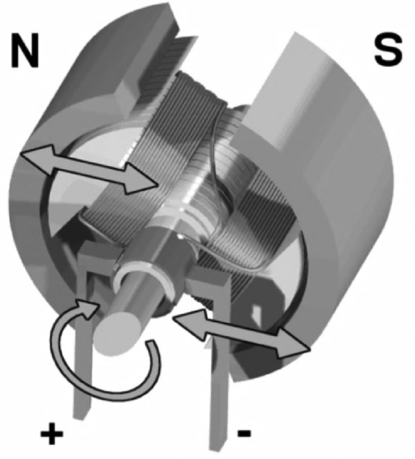
Fig. 10.29 Generator under load.
The current flowing (which can be single-phase, three-phase, or multi-phase) through the stator provokes the magnetomotive force: it is the armature reaction. Under these conditions the resulting flux in the machine because of the magnetomotive force (Fmme) (Fig. 10.30) and the armature reaction magnetomotive force (Fmmi). The flow of a balanced three-phase system of currents through the armature (stator) feeding balanced three-phase loads (which is how generators work) produces a rotating speed field. We define it (Eq.
as:
(10.17)
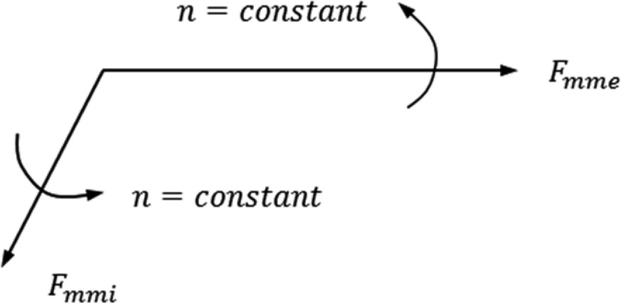
Fig. 10.30 Two rotating vectors. Source: own elaboration
Taking into account the frequency of the currents passing through the armature and the fact that the generators have the same number of poles in both the stator and the rotor, we deduce Eq. 10.18.
(10.18)
The reaction in the armature rotates at the same speed and in the same direction as the inductor rotating field that the rotor creates. Then we have two phasors that rotate in solidarity at synchronous speed (Fig. 10.31). Therefore, when a synchronous generator is idle, it is the rotor that creates the only existing rotating field in the machine.
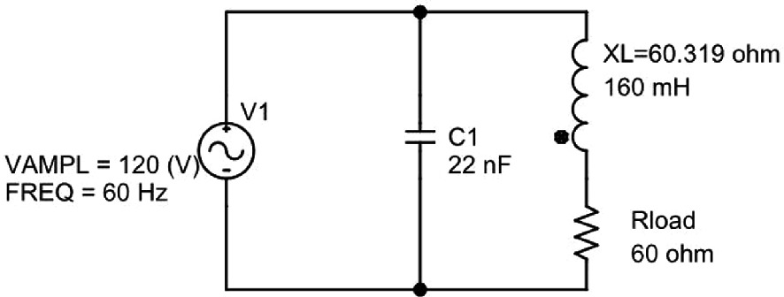
Fig. 10.31 Capacitor in an inductive circuit. Source: own elaboration.
The rotating field induces the emf in the stator windings:
(10.19)
Question What is the emf value that the rotating field induces in the stator windings?
When the generator works under load, the terminal voltage differs from the no-load voltage. This is because the stator windings and the load are both subject to AC current flow. These currents cause the armature reactive field to rotate at the synchronous speed n.
练习题
A synchronous generator has a no-load terminal voltage of V per phase. When operating under load with the same excitation current, the terminal voltage drops to V per phase. What is the voltage regulation coefficient ?
Which of the following statements correctly describe the rotating magnetic fields in a synchronous generator?
When a synchronous generator operates under load, the armature reaction field rotates at synchronous speed , which equals the rotor speed given by , where is the frequency of the induced voltage and is the number of pole pairs.
The RMS value of the EMF induced in the stator windings per phase is given by the equation , where is the number of turns per phase, is the magnetic flux per pole, and is the frequency.
Explain why the terminal voltage of a synchronous generator under load differs from the no-load voltage , even when the excitation current remains constant.
登录后解锁笔记、知识点解析、AI 问答
立即登录