正在学习
10.4 Real Synchronous Generator
10.4 Real Synchronous Generator
An authentic synchronous generator has the inductor in the rotor and the armature in the stator. In a generator with a set of poles, the direct current that flows through the rotor winding establishes the poles, designating the north and south poles based on the current flow (Fig. 10.18). The rotor-air gap-stator path encloses the magnetic field force lines.
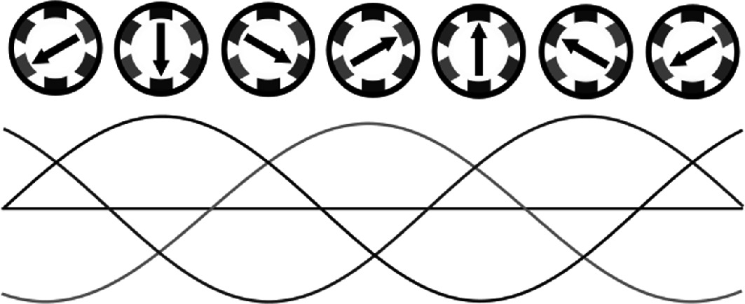
Fig. 10.18 Synchronous generator induced waves. Source from wikicommons under free to use license [12]
Question What do we get if we use an external drive mechanism to rotate the poles? As we know, rotating the poles by means of an external drive, like a turbine, it appears a rotating magnetic field.
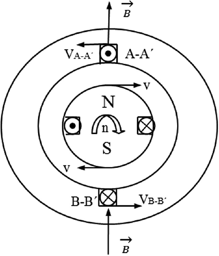
Question What does represent a rotating magnetic field in a real synchronous generator? A rotating magnetic field moves with respect the stator coils. The application of Faraday's law results in the generation of an emf in the stator coils. These conductors do not move. Faraday's law requires taking the conductor's velocity regarding the field (A−A′) into account in order to determine the polarities of the induced electromotive forces in the stator conductors.
However, in the machine, it is the field that moves relative to the conductor (v). We see that the rotor's rotation causes a polarity change of the induced electromotive forces in the windings (Fig. 10.19). Specifically, the forces enter under the North Pole and exit under the South Pole (in the rotation direction).
 indicating the magnetic field direction.">
Fig. 10.19 Polarity of induced electromagnetic forces. Source: own elaboration
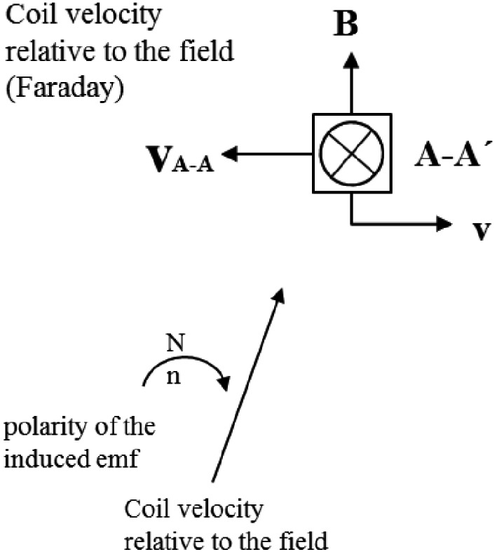
According to Faraday's law, we have to plot relationship between coil speed and electromagnetic forces (Fig. 10.20).
 moving relative to a magnetic field , with direction indicated by arrows. The bottom section depicts the polarity of the induced electromotive force (emf) with an arrow labeled and , showing the direction of coil velocity relative to the field.">
Fig. 10.20 Relationship between coil speed and electromagnetic forces. Source: own elaboration
Diagram illustrating electromagnetic induction. A straight arrow points diagonally upward, labeled "Coil velocity relative to the field." A curved arrow labeled "" and "" indicates the direction of rotation, with the text "polarity of the induced emf" nearby. The sketch represents the relationship between coil movement and induced electromotive force.
The rotation of the stator will induce a total emf in them.
E = 4.44·N·Φ₀·f (10.11)
As with transformer windings, and asynchronous machines these turns have some resistance and reactance.
练习题
In a real synchronous generator, where are the inductor and armature located?
According to equation , what does the variable represent?
What is created when an external drive mechanism, such as a turbine, rotates the poles of a synchronous generator?
Which of the following statements about a real synchronous generator are correct?
In a real synchronous generator, the stator conductors move with the rotating magnetic field to generate an electromotive force.
The rotation of the rotor in a synchronous generator causes the polarity of the induced electromotive forces in the stator windings to change.
In a real synchronous generator, the induced electromotive forces enter the stator conductors under the South Pole and exit under the North Pole in the direction of rotation.
The magnetic field force lines in a synchronous generator follow the ___-air gap-stator path.
The total induced emf in the stator windings is given by the equation ___.
Explain how a rotating magnetic field induces an electromotive force in the stator coils of a real synchronous generator.
Compare the structural configuration of a basic (elementary) synchronous generator with that of a real synchronous generator in terms of where the inductor and armature are located.
In an elementary synchronous generator (Section 10.3), the armature rotates within a stationary magnetic field, while in a real synchronous generator (Section 10.4), the field rotates while the armature remains stationary. Despite this structural difference, both configurations produce the same induced emf equation . What principle explains why both configurations yield equivalent results?
In a real synchronous generator, direct current powers the rotor winding to establish magnetic poles, and when an external drive rotates these poles, the resulting rotating magnetic field induces an alternating emf in the stationary stator coils according to Faraday's law.
In an elementary synchronous generator, the armature moves through a stationary magnetic field, whereas in a real synchronous generator, the magnetic field moves relative to stationary conductors. Both configurations produce the same RMS emf value given by the equation ___ .
Which of the following statements correctly describe the relationship between elementary synchronous generators (Section 10.3) and real synchronous generators (Section 10.4)?
登录后解锁笔记、知识点解析、AI 问答
立即登录