正在学习
10.3 Elementary Synchronous Generator
10.3 Elementary Synchronous Generator
The basic synchronous generator includes a stationary inductor in the stator and a movable armature in the rotor. The most elementary arrangement consists of two-pole elementary generator (Fig. 10.14).
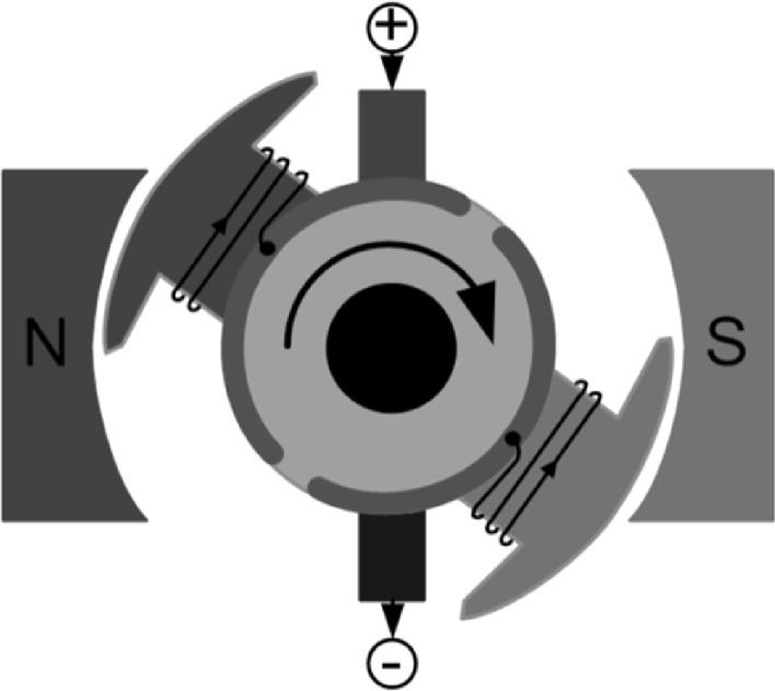
Fig. 10.14 Stator core and two-pole rotor. Original from haade. Source original from wikicommons under CC3.0 use license [11]
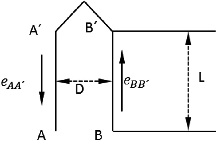
Examining a basic generator, we find that it consists of a cylindrical rotor with a diameter D and an axial length L, matching the depth of the poles, and a stator or inductor with two poles, north and south. It is of vital importance to understand the distance in windings (Fig. 10.15).
 and , while a horizontal dashed line represents distance . Another vertical dashed line on the right side is labeled .">
Fig. 10.15 Elementary synchronous generator stator windings. Source own elaboration
In the rotor (Fig. 10.16), we have a loop comprising two conductors, AA′ and BB′ that connects to a conductor A′B′. This conductor is not within the field of influence of the magnetic field.
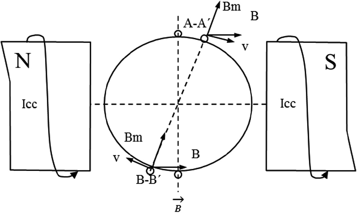
Fig. 10.16 Rotor wiring scheme. Source own elaboration
When the rotor rotates at n rps, the linear velocity of loops AA′ and BB′ is:
v=ω·radio=2π·n·D2=π·n·D (10.2)
According to Faraday's law, when moving coils AA′ and BB′ within a magnetic field, induced voltages are:
eAA′=v·B·L·senθ (10.3)
eBB′=v·B·L·senπ-θ (10.4)
Keep in mind that both voltages have the same magnitude and direction (Fig. 10.17). The induced emf within the loop is then:
eAB=2·eAA′=2·v·B·L·senθ=2π·n·D·B·L·senθ (10.5)
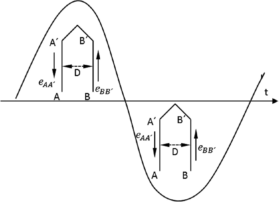
Fig. 10.17 Basic synchronous generator stator. Source own elaboration
The flux that the loop embraces is at its maximum value when it is vertical and perpendicular to the lines of the magnetic field and becomes:
Φ0=B·D·L (10.6)
D-L is the part that is inside the loop at the position of maximum flow.
Therefore, it is true that:
eAB=2π·n·Φ0·senθ (10.7)
The total emf in the N loops is:
e=N·2π·n·Φ0·senθ (10.8)
Recalling the definition of angular displacement θ, we have:
θ=w·t=2·π·n·t
Therefore, in the case of N turns, the emf is a sinusoidal function of magnitude. Substituting this equation into (Eq. 10.9) we have that:
e=N·2π·n·Φ0·sen2π·n·t (10.9)
Upon a comprehensive analysis of a rotor's complete rotation, it becomes evident that loops AA′ and BB′ change polarity, depending on whether they are under the influence of the North or South Pole.
Each turn guarantees a complete emf cycle. It is important to note that the coils have a polarity during the first half-cycle, and the opposite in the second half-cycle.
The value of this emf is then:
E=2·π·N·f·Φ02=4.44·N·Φ0·f (10.10)
练习题
In a basic synchronous generator, which component is stationary and which is movable?
A synchronous generator rotor has a diameter m and rotates at rps (revolutions per second). What is the linear velocity of the rotor loops?
What is the RMS value of the emf generated by a synchronous generator with turns, maximum flux Wb, and frequency Hz?
Which of the following statements correctly describe the induced voltages in the rotor conductors AA' and BB' of an elementary synchronous generator?
The maximum flux embraced by the rotor loop occurs when the loop is horizontal and parallel to the magnetic field lines.
In a synchronous generator, the rotor conductors AA' and BB' maintain the same polarity throughout a complete rotation.
Unlike asynchronous motors where the rotor speed is reduced by slip, synchronous generators rotate at a constant speed determined by the number of poles and the network frequency.
The RMS value of the emf in a synchronous generator with N turns, maximum flux , and frequency f is given by the formula:
The angular displacement of the rotor is related to the rotational speed (in rps) and time by the equation:
Explain why each complete turn of the rotor in a two-pole synchronous generator produces one complete cycle of emf.
登录后解锁笔记、知识点解析、AI 问答
立即登录