正在学习
9.8 Asynchronous Motor Operation
9.8 Asynchronous Motor Operation
The stator creates a three-phase current system with i1 (t), i2 (t), and i3 (t) flowing through its windings when its three phases receive a balanced three-phase voltage system (as shown in the right figure above). According to Ferraris' theorem, this current system produces a rotating field at a constant speed. We can plot the rotation of the magnetic field that the stator phases generate (Fig. 9.23). The rotor follows the rotating magnetic field but rotates asynchronously, at a lower speed.
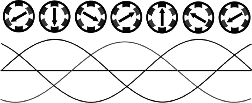
Fig. 9.23 Three phase voltage induction waveform. Source: from wikicommons under free to use license [12]
According to Faraday's and Lenz's law, it appears magnetic flux due to induced rotor current (Fig. 9.24).
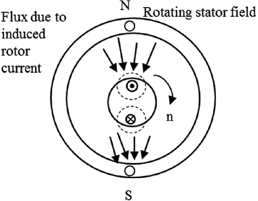
Fig. 9.24 Flux due to induced rotor current. Source: own elaboration
The rotor windings experience electromotive forces because of this rotating field. Current flows through the rotor windings as a result of the connections made between them, either by short-circuiting the windings with the rings in the squirrel cage, or by connecting the ends and beginnings. These groups of currents, under the influence of a magnetic field, generate forces and torques according to Laplace's law. Below we see the forces and components over a squirrel-cage rotor (Fig. 9.25).
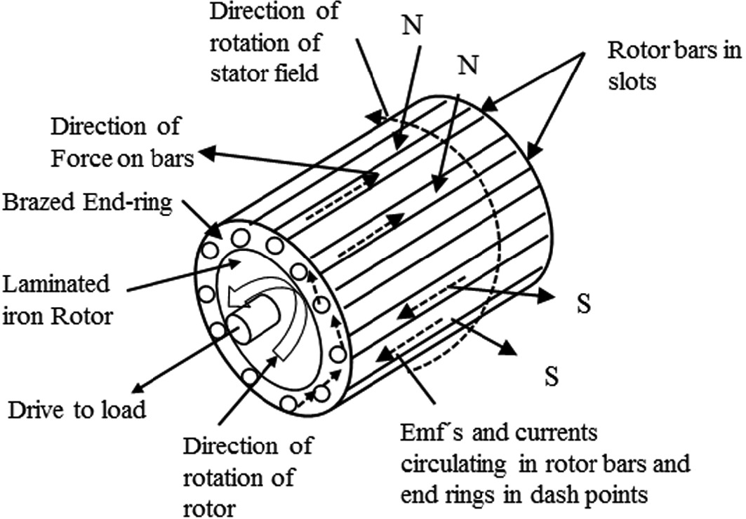
Fig. 9.25 Direction of forces in a squirrel-cage induction machine. Source: own elaboration
These forces and torques system rotate the rotor at a speed n2 in similar direction as n1. However, it is important to note that the final rotor speed, n2, never equals n1 due to Faraday's law, which requires a relative speed between the magnetic field and conductor (Fig. 9.26).
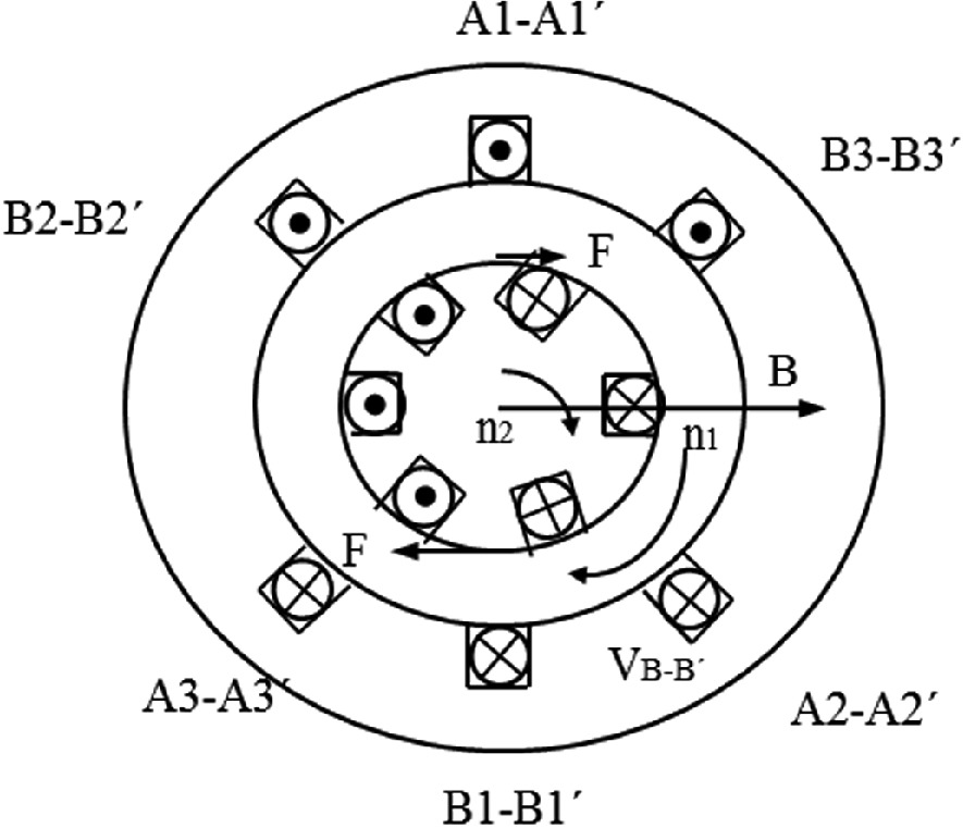
Fig. 9.26 Relative speed between rotor and magnetic flux. Source: own elaboration
Keep in mind that the rotor and magnetic flux speed are very close, but they are not similar. When the rotor rotates at n2, the slip velocity (nS) between the rotor and the stator rotating field causes the frequency of the rotor's electromotive forces as well as the frequency of the rotor currents to occur. This frequency is expressed as:
fs = p·ns/60 = p·s·n1/60 = s·f1 (9.5)
In a vacuum, meaning that no load connects the rotor shaft, the rotor speed is almost the same of the magnetic field. Consequently, nS is almost zero. When the machine is loaded, the speed increases but it is still close to zero. A low nS value suggests that the frequency of rotor currents is low, lowering the iron losses in the machine's rotor. Therefore, the sheet of metal that we use to manufacture rotors is of lower quality than the sheet metal we use to make stators.
练习题
Why does the rotor speed in an asynchronous motor never equal the synchronous speed of the rotating magnetic field?
In an induction motor, if the stator supply frequency is Hz and the slip is , what is the frequency of the rotor currents ?
Which of the following physical laws are directly involved in the operation of an asynchronous motor?
According to Ferraris' theorem, a balanced three-phase current system in the stator windings produces a rotating magnetic field at constant speed.
The rotor of an asynchronous motor rotates in the opposite direction to the rotating stator magnetic field.
When an asynchronous motor operates with no load connected to its rotor shaft, the slip velocity is almost zero.
The slip velocity () between the rotor and the stator rotating field causes the frequency of the rotor's ___ as well as the frequency of the rotor currents.
Because the frequency of rotor currents is low during normal operation, the iron losses in the machine's rotor are ___, allowing lower quality sheet metal to be used for rotor construction compared to the stator.
Explain why the rotor of an asynchronous motor rotates at a lower speed than the synchronous speed of the stator's rotating magnetic field.
Describe how current flows through the rotor windings of a squirrel-cage induction motor and how this differs from a wound rotor.
A three-phase induction motor has its stator windings distributed in slots and connected in a star configuration. When balanced three-phase voltages are applied, these windings carry currents , , and . According to Ferraris' theorem, what is the direct result of this current system?
Which of the following statements correctly describe the relationship between the stator and rotor in an operating asynchronous motor? Select all that apply.
In a squirrel-cage induction motor, the rotor bars are short-circuited by end rings, and the stator's rotating field automatically creates an equal number of poles in both the rotor and stator.
When an asynchronous motor operates with no load connected to the rotor shaft, the rotor speed is nearly equal to the magnetic field speed, making the slip velocity almost ___.
Explain why the sheet metal used to manufacture rotors can be of lower quality than the sheet metal used for stators in an asynchronous machine.
登录后解锁笔记、知识点解析、AI 问答
立即登录