正在学习
4.8 RLC Series Circuit
4.8 RLC Series Circuit
When a resistor, a coil and a capacitor connect in series, the combined effect of R, XL and XC limits the current. We use Ohm's law to determine the value of the current. Combining the effects of R, XL, and XC determines the impedance Z. We use the same previous procedure to determine the values of Z and fi. The overall impedance of the circuit is R, XL, and XC. Note that because the three elements are in series, each will experience a voltage drop. As a result, the sum of the three voltage drops will result in the total voltage. A R-L-C series circuit that includes a resistor, an inductance and a capacitor (Fig. 4.22).
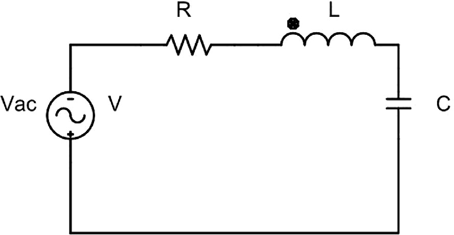
Fig. 4.22 R-L-C series circuit.
The voltage drops in each component are:
UR=R·I; This is the active or resistance voltage drop. UL=XL·I; This is the inductive voltage drop or inductive voltage. UC=XC·I This is the capacitive voltage drop or capacitive reactive voltage.
And their sum must equal the total voltage U.
Question What steps must we take to draw the vector diagram?
To establish the equivalence between these quantities, we will use vector diagrams again. According to Kirchhoff voltage law, U becomes the vector addition of these three voltages (Fig. 4.23):
U→=UR⇀+UL⇀+UC⇀ (4.54)
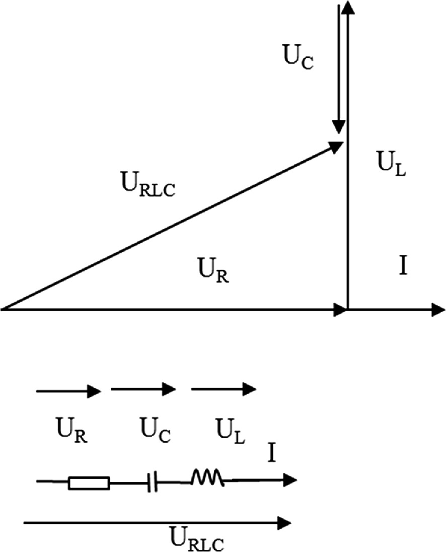 , , , and , representing voltage across the resistor, inductor, capacitor, and the total voltage, respectively. The current is also indicated. The bottom section depicts a circuit schematic with a resistor, inductor, and capacitor in series, with arrows showing the direction of current and voltages.">
Fig. 4.23 Phasor diagram of a series RLC circuit.
To draw the vector diagram, we follow the following steps:
- We draw the vector diagram with the current as a reference at wt=0 because it is common to R, L and C.
- We draw UR on the vector diagram in phase with the current because the ohmic resistance does not cause a phase shift.
- The voltage UL is 90º ahead of the current.
- The voltage UC delays 90º regarding to the current.
It is noted that the vector diagram shows an inverse relationship between the capacitor and coil voltage drops. The vector sum of UR, UL, and UC determines the system voltage U, which advances by an angle fi with respect to the current.
We can derive the voltage triangle from the vector diagram of the R-L-C circuit.
Because UR, and (UL – UC) compose the legs of a right triangle and U the hypotenuse of the triangle, it satisfies:
U=UR2+UL-UC2 (4.55)
The voltage triangle determines the angle phi, which corresponds to the phase difference between the voltage at the generator's terminal, U, and the current that flows through the circuit, I. The angle can be easily found (Eq. 4.56).
φ=arctgUL-UCUR (4.56)
If we divide the sides of the voltage triangle by I, the resulting impedance triangle is similar. Looking at the impedance triangle we have:
Z=R2+XL-XC2 (4.57)
and α=arctgXL-XCUR (4.58)
Then we can draw the impedance triangle of the R-L-C series circuit (Fig. 4.24).
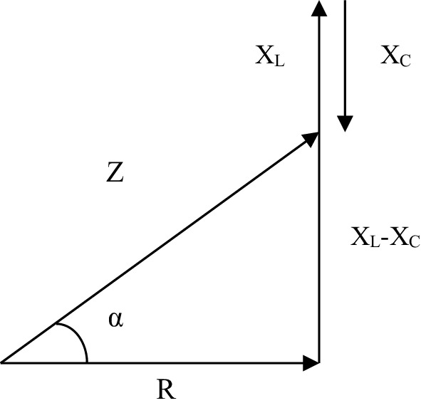
Fig. 4.24 Impedance triangle of the RLC series circuit.
In the impedance triangle we see that the capacitor partially compensates for the coil's reactance. This causes the circuit to behave like an inductive circuit, and this provokes a current delay (fi) relative to the voltage. Then, the capacitor compensates for some of the effects of the coil.
Question How do a coil and a capacitor behave in an RLC circuit?
In this scenario, the coil discharges the stored energy, some of which charges the capacitor. The capacitor returns the energy to the coil during the following quarter cycle. We express the impedance Z of the circuit as a function of R, L, and C by substituting the resistors' values (Eq. 4.57). Recalling that:
Xc=1C·ω (4.59)
and:
XL=ω·L (4.60)
We calculate the equivalent impedance (Eq. 4.61):
Z=R2+XL-XC2 (4.61)
Substituting Eqs. 4.59, and 4.60 we have (Eq.
练习题
In an RLC series circuit, what is the correct formula for calculating the total impedance ?
When drawing the phasor diagram for an RLC series circuit, why is the current used as the reference at ?
In an RLC series circuit where , how does the total voltage relate to the current in terms of phase?
Which of the following statements correctly describe the phase relationships between voltages and current in an RLC series circuit?
Which of the following equations correctly represent relationships in an RLC series circuit?
In an RLC series circuit, the impedance triangle is obtained by dividing each side of the voltage triangle by the current .
In an RLC series circuit, when , the circuit behaves capacitively and the current leads the voltage.
According to Kirchhoff's voltage law for an RLC series circuit, the arithmetic sum equals the total voltage .
In an RLC series circuit, the voltage drop across the resistor is calculated as , the voltage drop across the inductor is , and the voltage drop across the capacitor is ___.
The phase angle between the total voltage and current in an RLC series circuit is calculated using the formula \varphi = \arctan\frac{___}{U_R}.
Explain how the capacitor compensates for the coil's reactance in an RLC series circuit and what effect this has on the circuit behavior.
Compare the impedance formulas for RL, RC, and RLC series circuits. Explain how the RLC formula generalizes the other two.
In an RL series circuit, the impedance is . In an RC series circuit, the impedance is . Which formula correctly represents the impedance of an RLC series circuit, and why does it differ from the RL and RC formulas?
Which of the following statements about phase relationships are TRUE for ALL three circuit types: RL series, RC series, and RLC series circuits?
In an RL series circuit, the phase angle is calculated as and the current always lags the voltage. In an RC series circuit, the phase angle is and the current always leads the voltage. In an RLC series circuit, if , the circuit behaves like an RL circuit with current lagging the voltage.
In an RL series circuit, the voltage triangle has legs and , with the phase angle . In an RC series circuit, the voltage triangle has legs and . In an RLC series circuit, the voltage triangle has legs and ___.
Explain why the impedance triangle of an RLC series circuit can be derived by dividing each side of the voltage triangle by the current , and how this relationship was previously established for RL and RC series circuits.
登录后解锁笔记、知识点解析、AI 问答
立即登录