正在学习
4.7 Sinusoidal RC Series Circuit
4.7 Sinusoidal RC Series Circuit
When a resistor and a capacitor connect in series (Fig. 4.19), the combined effect of R and XC limits the current, as in the RL circuit. We can use Ohm's law to determine its value.
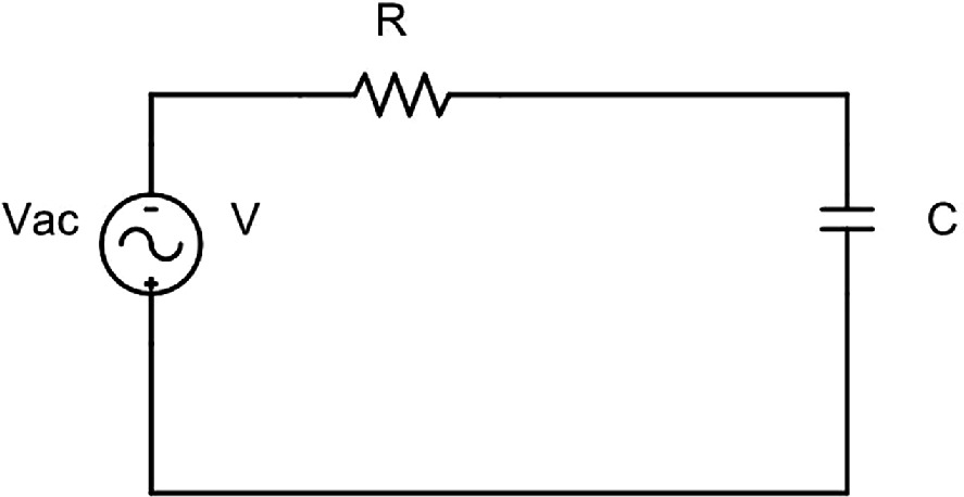
Fig. 4.19 Sinusoidal R-C circuit.
This law finds the impedance Z by combining the effects of R and XC. Then, we have:
I = U/Z
What is the difference in Z and angle phi with an RL circuit?
To find the value of Z and phi, we follow the same steps as in the previous case. However, the impedance now comprises the composition of the vectors R and XC, and the resulting phase shift will be a voltage delay.
Because R and C are in series, then there will be a voltage drop in each component. Therefore, the sum of the two voltage drops equals the total voltage. The voltage across each component is
VR = R·I Active or Resistance Voltage Drop (4.47)
VC = XC·I Capacitive voltage drop or capacitive reactive voltage (4.48)
And their sum must equal the total voltage V. We use vector diagrams to show the equivalence between these quantities. The voltage V is the sum vector of these two voltages which can be plotted in the phasor diagram of a series RC circuit (Fig. 4.20).
V→ = VR⇀ + VC⇀ (4.49)
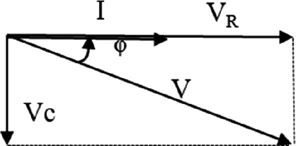
Fig. 4.20 Phasor diagram of a series R-C circuit.
To create the vector diagram, follow these steps. Begin by drawing the vector diagram with the current as a reference point in position wt=0, as this is typical for both R and C.
Question What steps must we follow to construct the vector diagram?
- We place VR on the vector diagram aligned with the current because the resistance does not cause any phase shift.
- The voltage VC is 90º out of phase with the current (advancing the current in phase with the voltage means delaying the voltage in phase with the current).
The vector addition of VR and VC, gives the resultant voltage V, which is phase-shifted by an angle fi relative to the current.
VR and VC compose the legs of a right angle, and V is the hypotenuse of it. It means that:
V=VR2+VC2 (4.50)
The voltage triangle also yields the phase difference angle between the generator terminal voltages V and the current through the circuit I. This angle is calculated as:
φ=arctgVCVR (4.51)
Similarly, the impedance triangle of the circuit, which includes R, and XC2 can be drawn (Fig. 4.21).
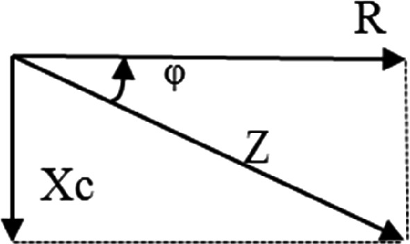
Fig. 4.21 Impedance triangle.
The impedance triangle, which is similar to the voltage triangle, can be obtained by dividing the values of its sides by I. The following holds true in the RC circuit impedance triangle:
Z=R2+XC2 (4.52)
φ=arctgXCR (4.53)
练习题
In a series RC circuit, the resistor has a value of and the capacitive reactance is . What is the total impedance of the circuit?
A series RC circuit has and . What is the phase angle between the voltage and current?
In a series RC circuit, the voltage across the resistor is and the voltage across the capacitor is . What is the total voltage ?
Which of the following statements correctly describe the phasor diagram construction for a series RC circuit?
In a series RC circuit, the voltage across the capacitor leads the current by 90°.
The impedance triangle of a series RC circuit can be obtained by dividing each side of the voltage triangle by the current .
In a series RC circuit, the combined effect of and limits the current, and the resulting phase shift produces a voltage delay.
In a series RC circuit, Ohm's law is applied to find the current using the formula , where is the total voltage.
The impedance magnitude of a series RC circuit is calculated using the formula .
Compare the phase relationship between voltage and current in series RC and RL circuits. What is the key difference in how the reactive component affects the phase angle?
In a series RL circuit, the inductive voltage leads the current by 90°, while in a series RC circuit, the capacitive voltage has a different phase relationship with the current. Which statement correctly describes this difference?
Both series RL and series RC circuits use the same formula structure for calculating impedance magnitude: , where represents the reactive component ( for RL circuits and for RC circuits).
Which of the following statements are true for BOTH series RL and series RC circuits? Select all that apply.
In a series RL circuit, the phase angle is calculated as , which results in a positive angle indicating that voltage leads current. In a series RC circuit, the phase angle formula is , which results in a ___ angle indicating that voltage lags behind current.
登录后解锁笔记、知识点解析、AI 问答
立即登录