正在学习
4.6 Sinusoidal RL Circuit
4.6 Sinusoidal RL Circuit
We restrict the current flow when we connect a resistor and an inductive reactance XL (Fig. 4.18).
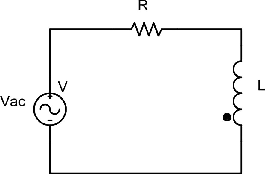
Fig. 4.18 Sinusoidal R-L circuit.
As the two elements are series-connected, the current that flows is similar for both elements. Ohm's law applies in this case, which we express as:
I = U/Z
We determine the impedance Z by combining the impact of R and XL. Since R and L are in series, there is a voltage drop in both elements. The total voltage is the sum of the two.
Applying Ohm's law the voltage drops are:
UR = R·I (Active or resistance voltage drop)
UL = XL·I (Inductive voltage drop or inductive reactive voltage)
And the sum must equal the total voltage U.
We will use vector diagrams to establish the equivalence between these quantities. Then, the total phasor voltage U is the sum of the two voltage phasors, and we express it as
U→ = UR⇀ + UL⇀ (4.42)
We follow the next steps to construct the vector diagram:
(1) We build the vector diagram with the reference current at the position of ωt = 0, as it is the usual case for R and L.
(2) We place UR on the vector diagram parallel to the current because resistance causes no phase shift.
Question How do we draw the vector diagram?
(3) The voltage UL is 90º ahead the current (delaying the current with respect to the voltage means advancing the voltage with respect to the current). UR and UL are the legs of a right angle, and U the hypotenuse of it. Then we can write:
U = √(UR² + UL²) (4.43)
The voltage triangle also yields the angle phi, which represents the phase difference between the voltage at the generator terminals (U) and the current flowing through the circuit (I). Then we have:
φ = arctg(UL/UR) (4.44)
We obtain the impedance triangle, which is similar to the voltage triangle by dividing its side by I. In this triangle the following holds true:
Z = √(R² + XL²) (4.45)
φ = arctg(XL/R) (4.46)
练习题
In a series RL circuit with resistance and inductive reactance , what is the total impedance ?
In a series RL circuit, the voltage across the resistor is and the voltage across the inductor is . What is the total voltage applied to the circuit?
What is the phase angle between the total voltage and current in a series RL circuit where and ?
Which of the following statements correctly describe the construction of a vector diagram for a series RL circuit? Select all that apply.
In a series RL circuit, the current flowing through the resistor is different from the current flowing through the inductor.
In a series RL circuit, the resistive voltage drop is in phase with the current because resistance causes no phase shift.
In a series RL circuit, the inductor voltage lags behind the current by 90°.
The impedance triangle is similar to the voltage triangle and is obtained by dividing each side of the voltage triangle by ___.
In a series RL circuit, the phase angle between the total voltage and current can be calculated from the impedance triangle using the formula: .
Explain why the total voltage in a series RL circuit is not simply the sum , and describe how it should be calculated instead.
In a series RL circuit, the inductive voltage leads the current by 90°. This phase relationship is a direct consequence of which fundamental principle of inductors?
A purely inductive circuit has impedance . When a resistor is added in series with the inductor, the total impedance becomes . What is the impedance if and ?
In a series RL circuit, the resistive voltage is in phase with the current because resistance causes no phase shift, while the inductive voltage leads the current by 90° because the self-induced emf opposes changes in current.
In a purely inductive circuit, the impedance equals the inductive reactance (). When resistance is added in series, the impedance is calculated using the formula , which shows that impedance is ___ directly proportional to either or alone.
Explain why the voltage triangle and impedance triangle in a series RL circuit are similar. Reference the inductive voltage drop formula in your explanation.
登录后解锁笔记、知识点解析、AI 问答
立即登录