正在学习
4.4 Purely Inductive Circuit
4.4 Purely Inductive Circuit
Let us connect the terminals of a sinusoidal alternating current generator and an ideal inductance. Similarly to capacitors, we can draw an alternating current source that connects to a coil (Fig. 4.11).
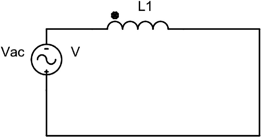
Fig. 4.11 Purely inductive circuits.
The voltage at the generator or inductance terminals is the same since there are not losses due to voltage drops.
Its mathematical expression is:
u = U0·senωt (4.25)
In any circuit where varying current flows, it appears an induced emf. The value of this emf source, which we express it in volts, is the product of the self-induction coefficient L, given in Hertz, and the rate of change of the current over time di/dt, given in amperes. Recalling the expression of the induced emf, eL:
eL = -L·di/dt (4.26)
The minus sign in Lenz's law shows that the induced emf, eL, in any coil because of a changing magnetic flux or field strength opposes the change that produces it.
Applying Kirchhoff's second law to the circuit, we get:
u + eL = 0 (4.27)
And substituting Eqs. 4.26 into (4.27) we have
u + -L·di/dt = 0 (4.28)
u = L·di/dt (4.29)
Substituting the instantaneous voltage value:
U0·senωt = L·di/dt (4.30)
Separating the variables in the differential equation yields:
di = U0/L·senωt·dt (4.31)
Only by integrating it we obtain:
∫di = U0/L·∫senωt·dt (4.32)
Therefore, it results in:
i = -U0/Lω·cosωt = U0/Lω·senωt - π/2 (4.33)
Since:
±cosωt = senωt ± π/2 (4.34)
Now:
I0 = U0/Lω (4.35)
Finally, we have:
i = I0·senωt - π/2 (4.36)
Now we plot the voltage and current waveform of a purely inductive circuit (Fig. 4.12).
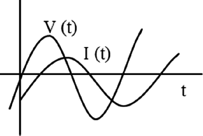
Fig. 4.12 Voltage and current through an inductance.
The current is then a sinusoidal function having the same frequency as the applied emf, but offset by π/2 radians from that voltage. Substituting (Eqs. 4.6 and 4.7) into Eq. 4.35 yields:
2·I = 2·U/ω·L (4.37)
Therefore, its root-mean-square (rms) value will be:
I = U/ω·L (4.38)
Substituting ωL in Eqs. 4.35 and 4.38 yields:
ω·L = U0/I0 = U/I = XLΩ (4.39)
When we express L in Henry and f in Hertz, and the units of ω·L = ohms. XL, also known as inductive or self-induction reactance, serves the same purpose as resistance and capacitive reactance in previous circuits by representing the coil's opposition to the passage of current.
Question Does the Joule effect occur? The Joule effect does not occur under a reactive load. It varies with the frequency, f, and also creates a –π/2 radian phase difference between voltage and current.
Now we plot the voltage, magnetic flux and current waveforms in a purely inductive circuit (Fig. 4.13).
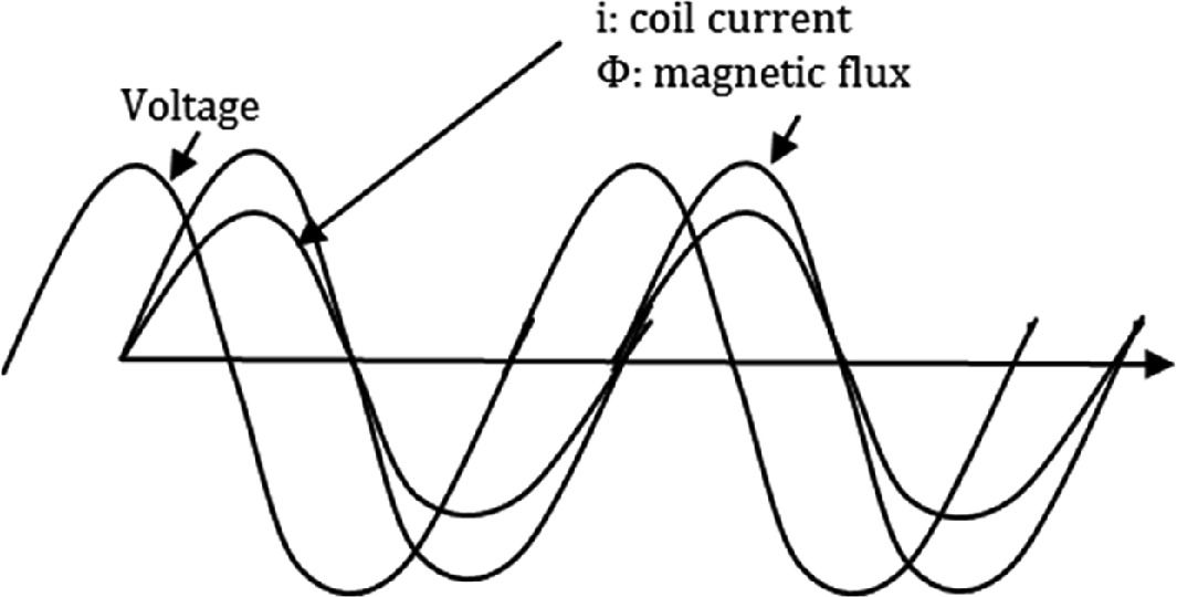
Fig. 4.13 Voltage, magnetic flux and current waveform through a coil.
One thing to keep in mind is that the current does not immediately follow the variations of the voltage, but rather exhibits "inertia" and lags behind the applied voltage. Inductances resist the flow of alternating currents through a reactance XL, which is proportional to the frequency (remember that ω = 2πf). Recalling Ohm's law for AC, in this case, the impedance of the circuit corresponds with the value of the inductive load Z = XL. We call "inductive voltage drop or inductive reactive voltage" to the voltage drop across the coil when the current I flow through it and we express it as:
UL = IXL (4.40)
When we connect a sinusoidal AC voltage source to an inductance, we can describe its behavior. Then, current wave lag behind the voltage wave in an inductive circuit (Fig. 4.14).
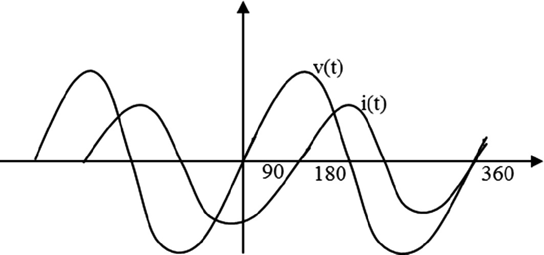 and on an X-Y axis. The horizontal axis is marked with angles 0, 90, 180, and 360 degrees, representing the phase of the waves. The vertical axis indicates amplitude. The waveforms illustrate phase differences, with leading .">
Fig. 4.14 Behavior of the current wave in inductive circuit.
When a sinusoidal AC current flows through the coil, the coil's magnetic flux lines intersect its own conductors.
练习题
In a purely inductive circuit, what is the phase relationship between the voltage and the current?
An inductor with inductance H is connected to an AC source with angular frequency rad/s. What is the inductive reactance ?
A purely inductive circuit has an applied voltage with V, rad/s, and inductance H. What is the peak current ?
Which of the following statements are true about a purely inductive circuit? (Select all that apply)
According to Lenz's law, the minus sign in the induced emf formula indicates that the induced emf opposes the change in current that produces it.
In a purely inductive circuit, the Joule effect occurs and causes power dissipation as heat.
When the frequency of an AC source increases in a purely inductive circuit, the inductive reactance decreases and allows more current to flow.
The self-induced emf in a coil is given by the formula ___ , where is the self-induction coefficient and is the rate of change of current.
In a purely inductive circuit, the instantaneous current can be expressed as ___ , showing that the current lags behind the voltage.
Compare the phase relationship between voltage and current in a purely inductive circuit versus a purely capacitive circuit. Explain why they are different.
In a purely capacitive circuit, the current leads the voltage by radians, while in a purely inductive circuit, the current lags the voltage by radians. What is the phase difference between the current and voltage in a circuit containing both a pure capacitor and a pure inductor connected in series to an AC source?
The capacitive reactance is given by and the inductive reactance is given by . How do these reactances change when the frequency of the AC source increases?
Both a pure capacitor and a pure inductor connected to an AC source consume zero average power because the Joule effect does not occur in purely reactive loads.
In a purely capacitive circuit, the current-voltage relationship is , meaning the current is proportional to the rate of change of voltage. In a purely inductive circuit, the relationship is , meaning the voltage is proportional to ___.
Explain why the current leads the voltage by radians in a purely capacitive circuit, while the current lags the voltage by radians in a purely inductive circuit.
登录后解锁笔记、知识点解析、AI 问答
立即登录