正在学习
4.3 Purely Capacitive Circuit
4.3 Purely Capacitive Circuit
Now we examine the charging and discharging process of a capacitor with AC sources.
When we apply a sinusoidal alternating voltage to a fully discharged capacitor, a strong charging current appears during the first quarter of cycle. Once the current source reverses the polarity, the capacitor discharges the stored energy, and so on (Fig. 4.6).
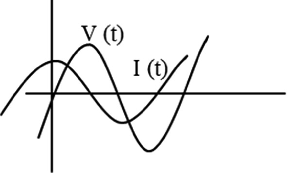
Fig. 4.6 Voltage and Current through a capacitor. Source: Own elaboration
Question: What happens to the voltage and current once the capacitor has been charged? Once the capacitor has been totally charged, we know that the current will reach zero and the voltage will be at its maximum.
When we plot the phasor diagram, the current waveform is 90 degrees ahead of the voltage waveform (Fig. 4.7).
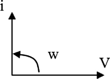
Fig. 4.7 Voltage and current phasor diagram. Source: Own elaboration
Expressing the sinusoidal voltage as
V(t) = Vm·sin(ωt) V (4.11)
Then, the voltage in the capacitor is also
Vc(t) = Vm·sin(ωt) V (4.12)
According to the constitutive law of the capacitor
Ic(t) = Im·sin(ωt + 90°) A (4.13)
This means that the capacitor advances the current by 90º with respect the voltage. Once the voltage source that feeds the capacitor falls, it discharges the stored energy during the previous quarter cycle, causing a discharge current to appear in the circuit.
Now on we will answer questions like:
Question: What is the charge-discharge time of a capacitor? , and what is the average electricity consumption? Because of the behavior of the capacitor, when we plot the current on the vector diagram (Fig. 4.7), we draw it at a 90° angle to the voltage. The average power that the capacitor absorbs is zero because it charges within one quarter of the cycle and returns it in the next quarter of the cycle. A pure capacitor advances the current by an angle of 90° to the voltage.
Question: Do you think the alternating current "I", will pass through the capacitor's dielectric? The alternating current that flows through a capacitor generates a sinusoidal electric current in the circuit. The continuous and alternating charging and discharging of the capacitor generates a sinusoidal electric current that flows through the circuit. We have to keep in mind that this current does not pass through the dielectric of the capacitor.
In order to determine the value of the current, we will use a capacitor with a capacity C that connects to the terminals of an alternator that delivers sinusoidal alternating voltage. When we designate the capacitor charge at instant t as q, we obtain:
q = C·U (4.14)
And as we know that:
i = dq/dt (4.15)
Combining Eqs. 4.14 and 4.15 yields
i = d(C·u)/dt = C·du/dt = C·d(U0·sen(ωt))/dt (4.16)
And therefore:
i = C·ω·U0·cos(ωt) (4.17)
However, as we know:
cos(ωt) = sen(ωt + π/2) (4.18)
It can be defined as:
i = C·ω·U0·sen(ωt + π/2) (4.19)
Remember that, according to the general expression of a sine alternating current wave, we obtain the instantaneous value of the current "I" as the projection on the y-axis of a rotating vector with a modulus equal to the maximum value, I0, which rotates counterclockwise.
Therefore, it follows that:
I0 = C·ω·U0 (4.20)
And thus, we can express the immediate value "I":
i = I0·sen(ωt + π/2) (4.21)
This equation shows that the current in a circuit with pure capacitance is a sine function of time, with the same frequency as the voltage source, but leading it by π/2 radians.
Note that we can express Eq. 4.21 as a function of voltage:
I0 = C·ω·U0 = U0/(1/(C·ω)), (4.22)
Then, we have
XC = 1/(C·ω)
We can plot the time-domain sinusoidal waveform as well as a rotating phasor diagram (Fig. 4.8).
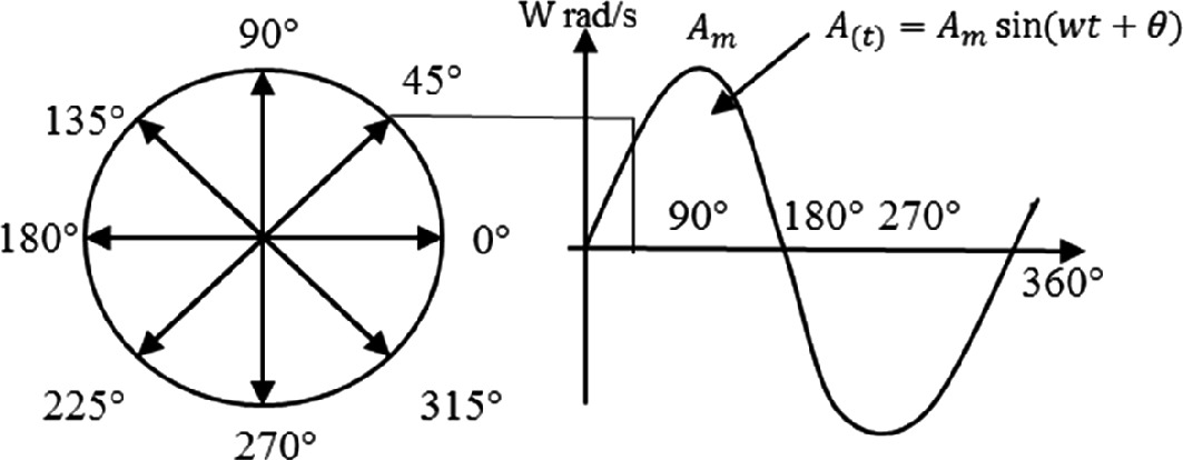
Fig. 4.8 Sinusoidal waveform in the time domain, with rotating phasor. Source: Own elaboration
We find the maximum current I0 using Ohm's Law by dividing the maximum voltage value U0 by the opposition to current passage when the instantaneous voltage value u equals U0. We can place a capacitor that connects to an alternating current voltage source (Fig. 4.9).
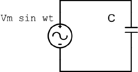
Fig. 4.9 Capacitor connected to a sinusoidal voltage source. Source: Own elaboration
Therefore, capacitive reactance or capacitance, denoted as Xc, characterizes the opposition presented to the flow of an alternating current by a capacitance of a circuit.
Taking the real part, we have:
I = U/XC (4.23)
In this case, the circuit impedance equals the value of the capacitive reactance (Eq. 4.1), using Ohm's Law for AC (Z = XC). We see that higher capacitor capacitance C results in lower capacitive reactance (Eq. 4.22). We also see that lower XC results in higher capacitor charging and discharging currents (Eq. 4.23). The higher the angular frequency of the sinusoidal current "w", the faster the capacitor charges and discharges and thus the current through the circuit increases.
It is important to keep in mind that the w is directly proportional to the frequency. As the frequency increases, XC will decrease. In an alternating current circuit, a capacitor represents a small resistance or a short circuit for high-frequency currents and a barrier for low-frequency currents. We could define direct current as having zero-frequency. It is to highlight that.
We measure regular frequency (f) in cycles per second (cps) or hertz (Hz), and angular frequency (w) in radians per second.
Then we know how to convert:
w = 2πf
The difference of voltage we have between the plates of a capacitor, that appears after current I, is known as the "capacitive voltage drop" or "capacitive reactive voltage".
We calculate this quantity as Uc = Xc·I = IC·ω (4.24)
Problem 4.1
We have a 175 μF capacitor that connects to a 230 V AC voltage source of a frequency of 50 Hz (Fig. 4.10). Determine the capacitive reactance and the current. Draw a vector diagram of U and I.
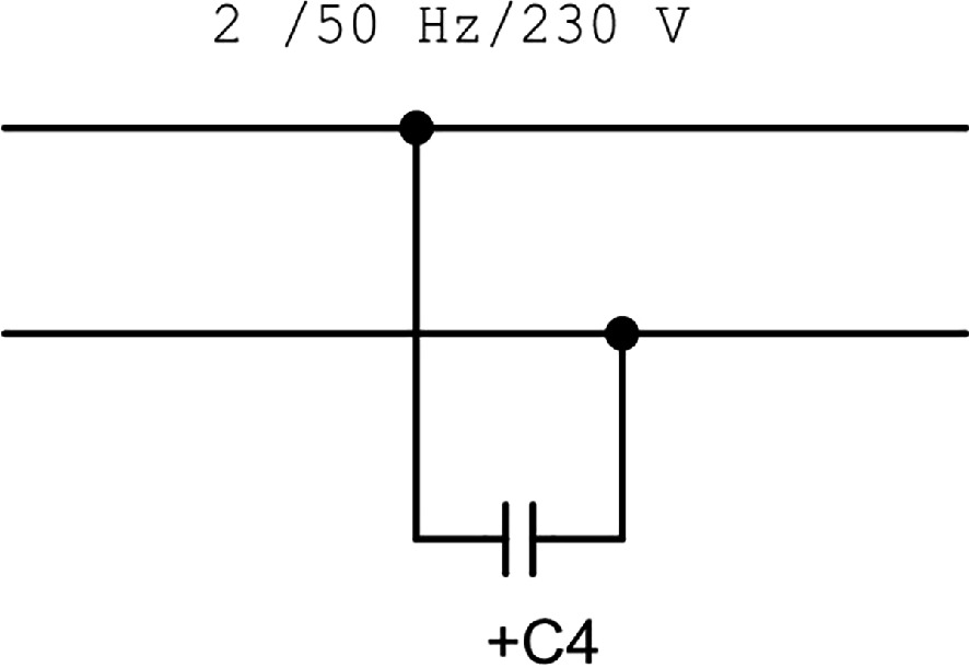
Fig. 4.10 Problem 4.1 Circuit with only a capacitor.
练习题
In a purely capacitive AC circuit, what is the phase relationship between the current and the voltage?
What happens to the capacitive reactance when the frequency of the AC source increases?
A capacitor with capacitance is connected to a sinusoidal voltage source with and angular frequency rad/s. What is the maximum current in the circuit?
Which of the following statements are true about a purely capacitive AC circuit? Select all that apply.
In a purely capacitive AC circuit, the alternating current flows through the dielectric material of the capacitor.
The average power absorbed by a pure capacitor in an AC circuit is zero because the capacitor stores energy during one quarter cycle and returns it during the next quarter cycle.
In a purely resistive AC circuit, the voltage and current are in phase, whereas in a purely capacitive AC circuit, the current leads the voltage by 90°.
The capacitive reactance is defined by the formula: X_C = \frac{1}{C \cdot \omega} = \frac{1}{___ \cdot C}, where is the frequency in Hertz.
When a capacitor is totally charged in an AC circuit, the current reaches ___ and the voltage is at its maximum.
Starting from the capacitor charge relation and the definition of current , explain how the expression is derived for a sinusoidal voltage .
In a purely resistive AC circuit, the voltage and current are in phase. How does this compare to a purely capacitive AC circuit?
For a purely resistive AC circuit, Ohm's law states that . What is the equivalent expression for a purely capacitive AC circuit?
When a sinusoidal alternating voltage is applied to a resistor, the instantaneous current can be expressed as . When the same voltage is applied to a capacitor, the instantaneous current is .
Which of the following statements correctly describe differences between purely resistive and purely capacitive AC circuits?
In a purely resistive AC circuit, the impedance equals the resistance (). In a purely capacitive AC circuit, the impedance equals the ___ ().
Explain why passive elements (resistors and capacitors) behave differently in AC circuits compared to DC circuits, specifically addressing the phase relationship between voltage and current.
登录后解锁笔记、知识点解析、AI 问答
立即登录